What’s new?
In an article published 2 October 2020 on the website of NIST (the US National Institute of Standards and Technology), KC Morris (leader of the Information Modeling and Testing Group in the Systems Integration Division of NIST) describes the new ASTM standard E3012-20, “Standard Guide for Characterizing Environmental Aspects of Manufacturing Processes.” This standard describes and builds on a Unit Manufacturing Process (UMP), which is shown in the following figure.
What does it mean?
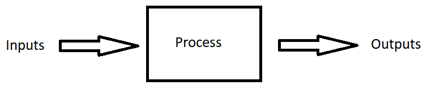
The simplest model of any manufacturing process involves identifying the inputs, the process, and the outputs, as shown at the top of this post.
Thus, when I make my breakfast, I use inputs (soy milk, yogurt, CBD oil, hemp protein powder, and frozen fruit), which I blend in a food processor to create the output, my breakfast smoothie.
There is a long history of modeling manufacturing process in such a way, with more details. My first faculty office at Purdue University was next door to the office of Alan Pritsker, one of the founders of the field of computer simulation, and from him I learned about the development of IDEF, Integrated DEFinition Methods in the 1970s, which in turn had been developed from SADT (Structured Analysis and Design Technique). Much of the work happened in the Air Force program ICAM (Integrated Computer Aided Manufacturing, which aimed to create standard data models. The basic element of IDEF0 (IDEF zero) is shown in this diagram:
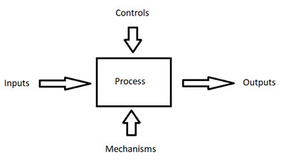
This diagram is the same as the simple Inputs-Process-Outputs diagram with the addition of Controls, which are the inputs that are used to direct the process, and Mechanisms, which are the inputs in the form of the resources and tools used to do the process. In my breakfast example, this expanded diagram allows the explicit identification of the recipe as the Control and the food processor as the Mechanism.
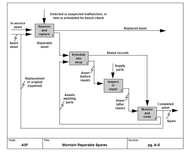
Obviously, in a manufacturing system the output from one process is input to the next process. IDEF0 blocks can be joined, resulting in a diagram such as this one showing the flow of physical objects and information:
This diagram is in the public domain.
These diagrams and concepts support thinking about processes and systems in manufacturing, resulting in systematic thinking (each process is documented and diagrammed in a similar way) and also systemic thinking (the relationship among processes is documented and can be studied).
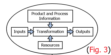
The newly proposed UMP is obviously a new version (or reinvention) of SADT and IDEF – and probably of some other similar diagrams that I am not familiar with. An expanded version of the UMP is shown below:
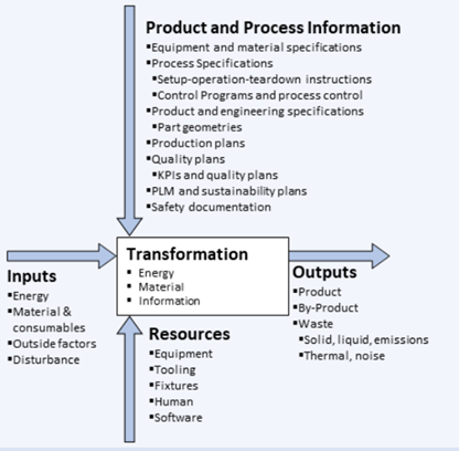
Credit: B. Bernstein/NIST
As compared to IDEF0, Transformation is another word for Process, Product and Process Information plays the role of Controls, and Resources the role of Mechanism. The difference from IDEF0 is that the emphasis in this new standard is on being able to describe and measure the environmental aspects of a manufacturing process. The standards are meant to help manufacturers better understand these environmental impacts and thus make better decisions about trade-offs among goals such as minimizing the use of resources and maximizing the speed of manufacturing.
What does it mean for you?
Systems thinking is a good thing. The simple step of drawing a line around a set of tasks and calling them a process seems trivial but it focuses one’s thinking on those tasks, it highlights the flow of material and information to support those tasks, and it supports the connection of those tasks to the previous and following tasks. With such thinking, a process then is a system, and it is part of a larger system.
Diagrams are good things. I always told my graduate students that we were well on our way with their work when we had a diagram that captured the basic ideas. As I have shown, the new UMP is not new, but the UMP diagram with arrows and labels is compelling: the concepts work, the words capture the ideas, and the lists associated with the major concepts make sure that the correct details are considered.
Finally, it really doesn’t matter which version of Inputs-Process-Outputs your organization uses. Pick a diagram, pick some words – even develop your own. Agree to use the diagram and the words throughout your organization and then get started on diagramming all the processes and systems. You will learn a lot about how your organization actually works if you make sure the results capture what is really happening and not just what is supposed to happen. You will certainly find that with some processes people don’t even agree on what is happening. A gemba walk (“gemba” is a Japanese word meaning, I am told, “the actual place”) will help; go and look at what is actually happening.
Where can you learn more?
Another example of the application of IDEF to furniture manufacturing is here. Dr Pritsker’s application of the IDEF methodology to modeling is described here.
Background on the issues that led to the development of the new ASTM standard are described in this 2016 paper.
ASTM, founded in 1898, used to stand for the American Society for Testing and Materials. Its name is now ASTM International.
There is so much available on process mapping that I hesitate to cite one or a few recommendations, but the ASQ (American Society for Quality) website is always a great starting place. Here is a good introduction from Netmind.
I’ll have a lot more to say about systems thinking in future posts.

This work is licensed under a Creative Commons Attribution 4.0 International License.